
Given the linkage Q2BCQ4EFH. Q2 and Q4 are fixed centers lying horizontally 6 in. apart with Q2 to left of Q4. Q2B is a crank 3 in. long and CQ4E is a lever 8 in. long pivoted at its mid point Q4, with C oscillating above the center line Q2Q4. BC is a connecting rod 7 in. long. EF is a link 8.5 in long driving a sliding block 8 and pinned to 8 at F, which moves along a horizontal line through Q2Q4 and to the right of Q4. MH and NH are links 2 in. long pinned to links EQ4 and EF, respectively, 2 in. from E. These link are pinned at H within the acute angle Q4EF. Q2B rotates counterclockwise at 30 rpm.
The problem was retrieved from Elements of Mechanism by Doughtie and James, p.470 - L-6.
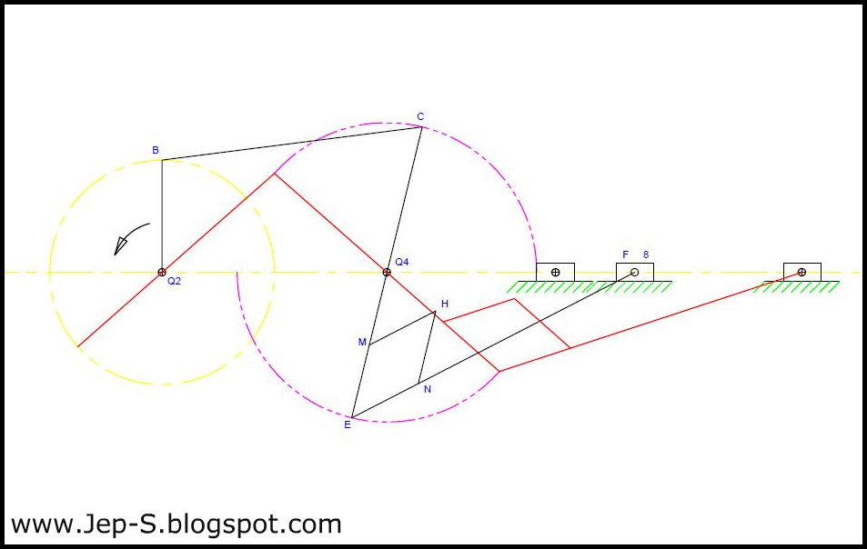 |
Click to enlarge |
I have drawn the figure using AutoCAD 2010. The main figure is colored black and the red one shows its extremity. The phantom line, colored as magenta, represents the extreme ends of the lever CQ4E as it oscillates.
Unfortunately, I wasn't able to finish the solution yet. I'm going to update this post whenever I confirmed my solution. If you see corrections on the figure, kindly throw a comment below. I hope this helps.